Capella Space
Blog
February 10, 2020
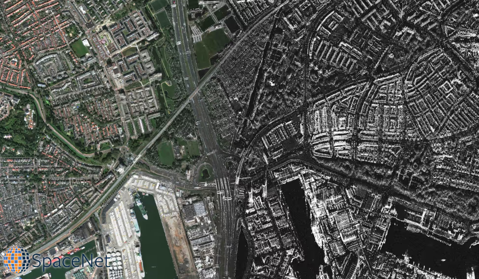
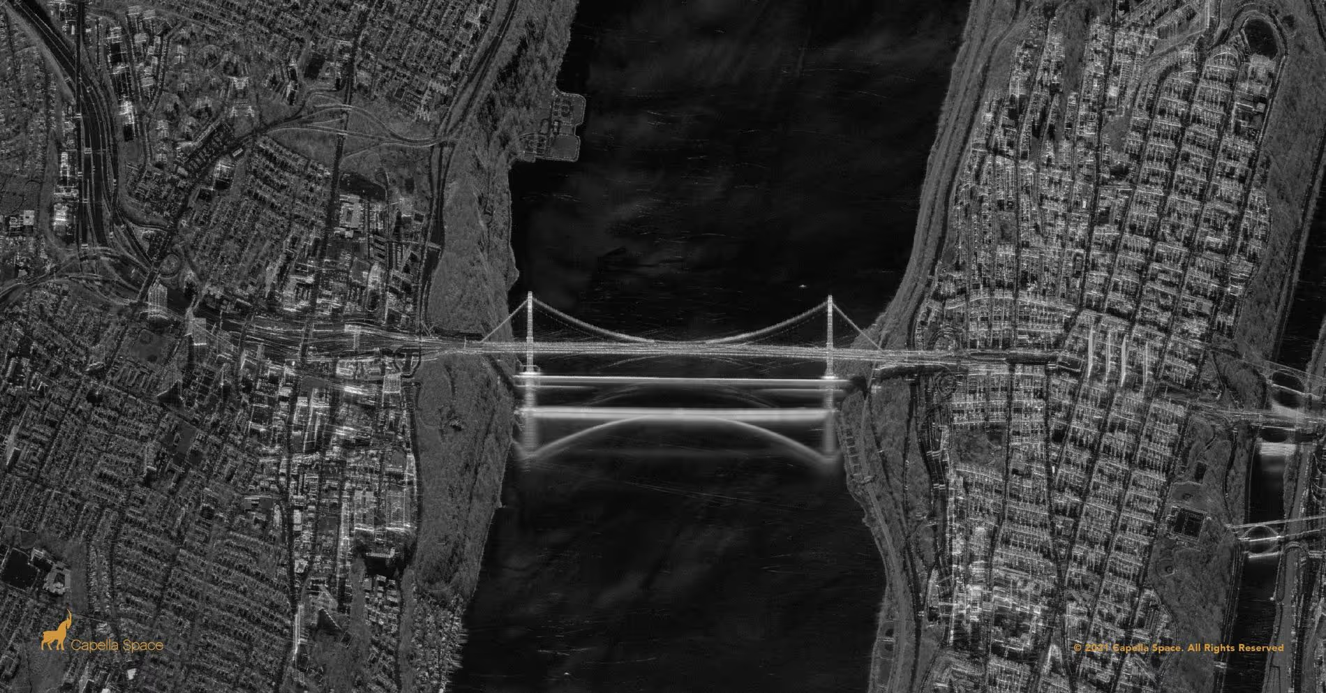
When asked to picture a “satellite image,” most people envision something like the left side of the figure above. It’s an optical image – a photograph – albeit one taken by a very powerful camera. But optical images are not the only way to visualize the earth’s surface from a satellite or an airplane.
Syntheticaperture radar, or SAR, is a completely different way to generate a picture by actively illuminating the ground rather than utilizing the light fromthe sun as with optical images. The right side of theimage above shows how very different SAR images look from optical images. Thesedifferences present challenges but also create new capabilities. One majoradvantage of SAR is simple: Even the best aircraft-mounted or satellite-mountedoptical camera is less uselful at night and useless when clouds or smoke arepresent. SAR can capture images at night and see right through clouds andsmoke. It is a 24-hour, all-weather technology.
SAR data will be featured in SpaceNet 6. In this two-part blog series, we’ll cover the basics of how SAR works, what makes it unique, and what makes it useful. Even (or especially) if you’ve never heard of SAR before, this series is for you!
How Does Synthetic Aperture Radar Work?
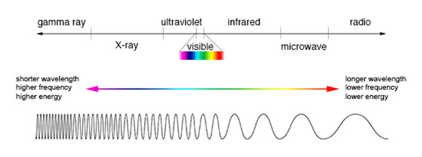
Synthetic aperture radar is a way of creating an image using radio waves. The radio waves used in SAR typically range from approximately 3 cm up to a few meters in wavelength, which is much longer than the wavelength of visible light, used in making optical images. These wavelengths fall within the microwave part of the spectrum in the figure below.
RADAR is an acronym for RAdio Detection AndRanging. Radar is an active system, which generates its own radio waves andtransmits them from its antenna, toward a target. Depending on the targetproperties and the imaging geometry, the radar antenna will receive all, some,or none of the radio wave’s energy (this is the Detection part of RADAR). Thisreceived signal will travel for an amount of time proportional to the target’sdistance from the antenna (this is the Ranging part of RADAR).
Real Aperture Radar (RAR)
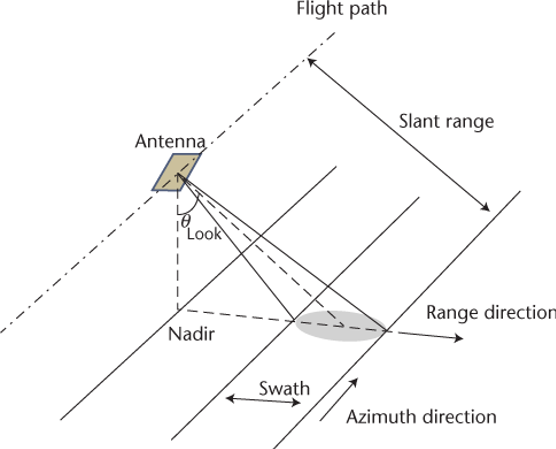
Side-imaging radar is different from a forward-looking radar, such as weather radar. If a radar antenna, which amplifies the transmitted and received signal, is carried in an airplane or an orbiting satellite, a radar can be used to make an image of the ground below. Forward looking radar cannot create images. Such a radar image is formed by transmitting pulses of radio frequency (RF) energy towards the ground and to the side of the aircraft, and measuring the strength of the return (sometimes called an “echo”) and the length of time it takes to make the round trip back to the antenna. In this manner, the ground is “scanned” in two dimensions. One dimension is the “range” dimension. Objects are placed along in this dimension according to their distance from the radar. The second dimension is the “along-track” (or “cross-range” or “azimuth”) dimension. In this dimension, the ground is scanned by the beam moving across the ground at a rate equal to the speed of the platform (aircraft or satellite), and objects are placed in this dimension according to the position of the aircraft along the track. An image is built up from the reflected signals in both dimensions.
Spatial resolution, the ability to resolve objects on the ground, differs in the range direction (perpendicular to the flight direction) compared to the azimuth direction (parallel to the flight direction). In “real aperture radar,” the range resolution is defined by the width of the pulses transmitted from the antenna. The azimuth resolution is determined by the width of the beam’s footprint on the ground, and the width of the beam is inversely proportional to the antenna length. A short antenna length corresponds to a wide beamwidth (beam footprint on the ground). Because flying an antenna large enough to generate a reasonable azimuth resolution, in space, is prohibitive, this limits the spatial resolution in the azimuth direction. The development of advanced processing algorithms solved this problem, leading to a new generation of imaging radars called Synthetic Aperture Radar.
Synthetic Aperture Radar (SAR)
To mitigate the undesired effects of real aperture radar’s poor azimuth resolution, the motion of the antenna along the azimuthal direction is utilized to “synthetize” or give the effect of a long antenna as shown in Figure 3.
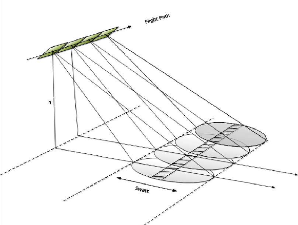
This synthetizing process is possible because a scatterer (target) on the ground remains within the real-aperture radar beam for many radar pulses. Adding up the reflections from all these pulses appropriately allows one to synthesize a large antenna with a much narrower beamwidth, resulting in a better spatial resolution in the azimuth direction. This technique is applicable for aerial systems as well as spaceborne systems.
SAR Image Interpretation
While the images created by SAR can be rendered into a recognizable terrain map, there are important differences between optical imagery and SAR imagery. SAR imagery is considered a non-literal imagery type because it does not look like an optical image which is generally intuitive to humans. These aspects must be understood for accurate image interpretation to be performed.
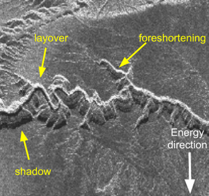
Shadowing
Shadowing is caused for the same reasons that shadows are formed in optical imagery: an object blocks the path of direct radiation—visible light in the case of optical imaging and the radar beam in the case of SAR. However, unlike optical imagery in which objects in shadows can be seen due to atmospheric scattering, there is no information in a SAR shadow because there is no return signal.
Foreshortening
Because SAR is a side-looking, ranging instrument, the backscattered returns will be arranged in the image based on how far the target is from the antenna along the slant plane (radar-image plane). This causes some interesting geometrical distortions in the imagery, such as foreshortening. As seen in Figure 4, the slope A-B is compressed in the slant plane because the radar signal reaches point B shortly after reaching point A in time. This causes a tall object with a slope, such as a mountain, to appear steeper, with a thin bright “edge” appearance. Note that the sensor’s look angle affects foreshortening; a larger look angle will decrease the effect.

Layover
Layover is an extreme example of foreshortening where the object is so tall that the radar signal reaches point B before it reaches point A. This causes the returns from point B to be placed on the image closer to the sensor (near range) and obscure point A, as if the top has been overlaid on the foot of the mountain.
The effects of these phenomena are altered depending on the sensor’s look angle. A larger look angle increases the effect of shadows (lengthening the shadow), while minimizing the effect of layover (less layover). A smaller look angle has the opposite effect. Figure 6 gives examples of these effects on rugged terrain. Figure 7, meanwhile, shows an example of how buildings in an urban setting are distorted by the same effects. All tall buildings appear laid out horizontally because of layover.

Pixel Brightness
While a radar image can look like a monochrome optical image, this impression is deceptive. The intensity of pixels in a radar image are not indicative of the color of the object (as in a color photograph). Instead, the intensity depends on the amount of energy the SAR sensor transmitted (like the brightness of the illumination source), the material properties of the object, the physical shape of the object, and the angle from which the object is viewed.
Sensor Parameters
Design and operation parameters allow engineers to have control over the reflected return signal (called backscatter). Engineers design and model the system and operating parameters to maximize radar returns and therefore the information collected against specific targets. During the design, the system’s wavelength and polarization (discussed below) are chosen and once launched, cannot be changed. These fixed sensor parameters dictate at some level the resulting brightness of a pixel in a particular image.
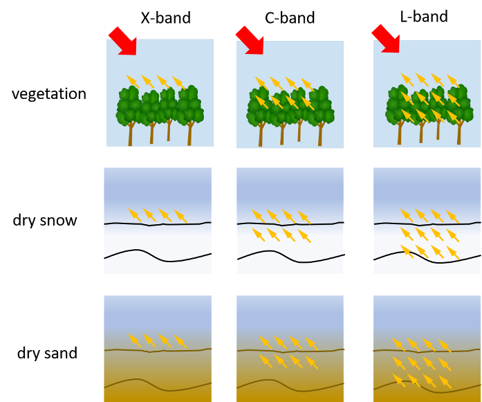
The wavelength affects the azimuth resolution but it also has important implications for penetration, see Figure 8. In general, radar penetration increases with wavelength.
The look angle affects layover and shadow as described above but can also have an effect on pixel brightness because it changes how the radar beam interacts with the object.
The polarization on transmit and on receive also affect the pixel brightness as described in the following section.
Implementing all of these improvements, however, did require making difficult choices. We delayed commencement of service by 8 months to complete and validate Sequoia’s evolved design. The satellite also doubled in size, increasing from 48 kg to 100 kg. Yet despite these choices, we are thrilled with the outcome—a world-class SAR satellite that delivers what our customers need and expect.
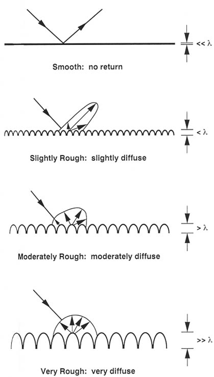
Surface Parameters
The surface parameters that affect pixel brightness are the surface roughness of the material, with respect to the system wavelength and the scattering material (the dielectric constant of the object). If the surface roughness of the material is smooth with respect to the system wavelength, the radar beam is reflected (Figure 9) according to the law of reflection. This is called specular reflection. If the surface is rough with respect to the system wavelength, the radar beam is scattered in all directions. This is called diffuse scattering. Varying surface roughness results in varying amounts of diffuse scattering and varying pixel brightness. The dielectric constant of the scattering material is a physical property of a material that determines how reflective that material is to electromagnetic waves. Metallic objects and water have a higher dielectric constant and are more reflective, however since they are smooth with respect to the system wavelength, and usually flat, the radar beam is specularly reflected, away from the sensor.
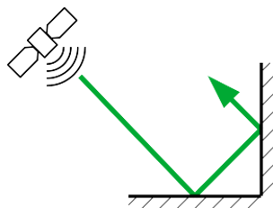
Additionally, certain surface features willcause a specular reflection back toward the sensor, by bouncing off multiplesurfaces. A Double-bounce reflectionis called a dihedral return and a Triple-bounce return is called a trihedralreturn. These are caused by smooth surfaces oriented at 90 degree angles toeach other as seen in figure 10.
Speckle
SAR is a coherent imaging method because the radio waves in a radar beam are aligned in space and time. This coherency provides many advantages (it’s required for the synthetic aperture process to work), but it leads to a phenomenon called speckle. Speckle is a “salt and pepper” variation in the pixel brightness that degrades the quality of the SAR images, making image interpretation more difficult. Speckle occurs because there are often many individual scatters in a given pixel, which leads to positive (salt) and negative (pepper) interference across pixels with an otherwise constant backscatter return.
What's Next
This post has described how SAR images are produced. By using clever signal processing, SAR creates radar images of higher resolution than would otherwise be possible. SAR imagery provides information about what’s on the ground, but distortions and speckle make these images very different from optical images.
In the second part of this two-part series, we’ll look at some of the special data analysis methods used with SAR and explore what makes SAR useful over optical imagery. That will be the subject of our upcoming installment, “SAR 201.”
Thanks to Adam Van Etten and Ryan Lewis.
Curious Which Of Our Analytics Partners
Can Support Your Mission?
Contact our team to explore the possibilities. Our experts can help
you determine the optimal solutions for your unique needs.

Keywords
Stay Informed. Stay Ready.
Get briefings on new capabilities, technology improvements, and upcoming events.


.avif)
