Back to Resources
Blog
Solving SAR’s Largest Bottleneck: How Acadia-10’s Optical Communications Terminal Is Redefining Latency
Capella Space
Blog
June 23, 2026
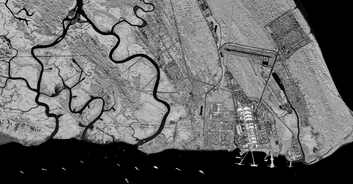
Synthetic Aperture Radar (SAR) data has always had a time problem. The imagery is remarkable: the radar works in all weather, day or night, resolving individual vehicles from 600 kilometers up. The struggle has never been collecting the data. It's been getting it to the people who need it fast enough to matter.
For most commercial SAR, task-to-delivery can be 3 to 8 hours. The industry has come to define leading as whoever can shave a few minutes off that window. But minutes off of hours misses the point. Three hours is a lifetime when a mission commander is tracking a convoy, when a disaster analyst needs to know which roads survived a flash flood, or when an intelligence team has to confirm activity at an airfield before the window closes.
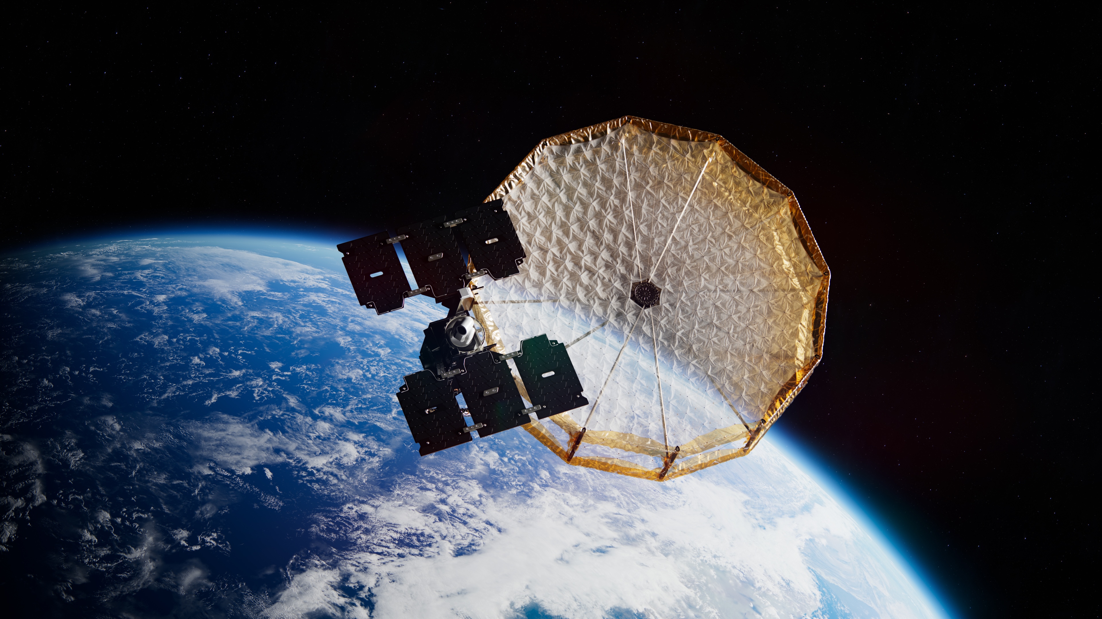
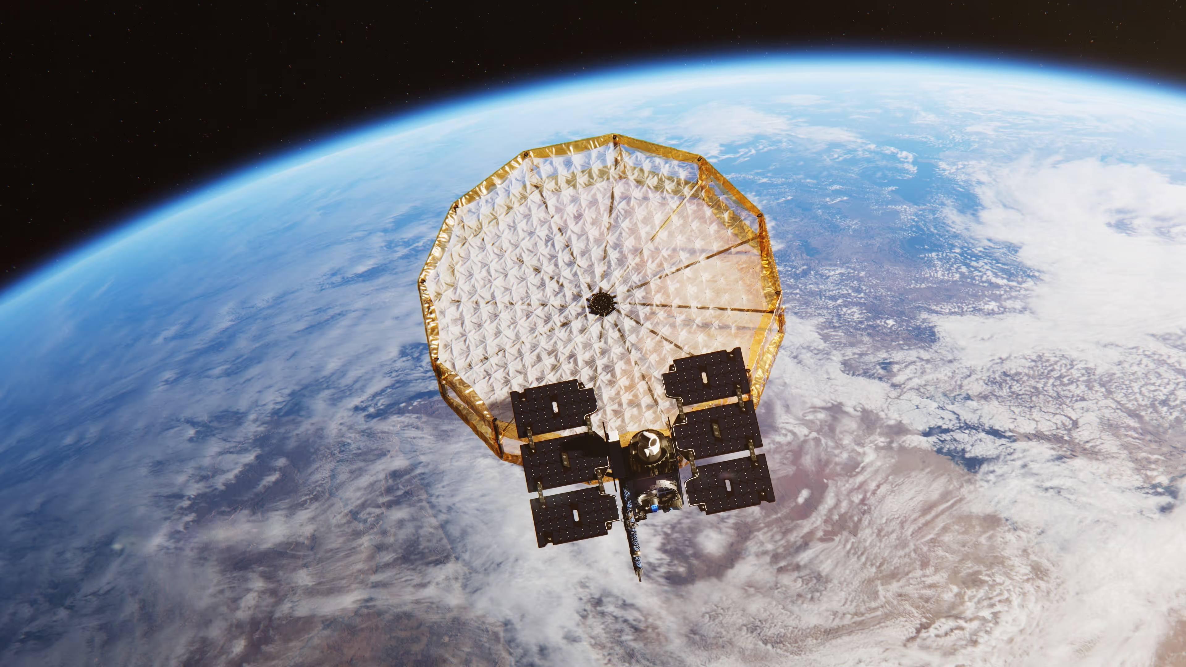
Our Acadia-10 satellite explores a different approach to addressing that latency through the integration of an Optical Communications Terminal (OCT), a technology designed to reduce some of the delays inherent in traditional SAR data delivery.
Why SAR Latency Has Been Stuck
To understand why OCTs matter to SAR, let’s understand where latency comes from in the data downlink chain. Most people assume the bottleneck is bandwidth. The SAR satellite collects a lot of data and the pipe to the ground is narrow. Although that’s part of it, the more insidious latency driver is geography constraints.
A low Earth orbit (LEO) SAR satellite is moving at roughly 7.5 km/s. If the satellite collects imagery over a target in Southeast Asia, it may need to orbit for 20 to 60 minutes before it is within line-of-sight of a downlink station. That wait is pure latency. The data sits on board, at rest, while the satellite travels toward a contact opportunity.
Traditional X-band RF downlinks have addressed this by deploying more ground stations, spreading them geographically to reduce the average gap between collection and downlink opportunity. Today, our SAR constellation follows that method using a global X-band ground station network achieving this exact goal. But physics imposes a ceiling. You cannot put ground stations everywhere. It is important to acknowledge that the downlink rate matters too. However, X-band downlink throughput is limited by the available spectrum bandwidth, so the latency reduction gains will be limited.
The result is a system where radar data is delivered to the customer at an industry standard of 3-8 hours. The addition of optical communications on Acadia-10 is intended to help address both the time-of-flight and throughput constraints that contribute to SAR latency.
OCTs close the gap between satellite and ground station data delivery constraints.
An Optical Communications Terminal uses a free-space laser link rather than a radio-frequency signal to transmit data. Here’s what’s different:
- Optical inter-satellite links operate in the largely atmosphere-free environment between satellites in LEO. Data can be routed across the mesh to a transport-layer satellite positioned over a ground station that is not affected by weather, turning what looks like a weather problem into a geometry problem the constellation solves.
- Optical communications terminals support data rates from 100 Mbps to tens of gigabits per second, and in the near future, hundreds of gigabits per second. Acadia-10 is currently conducting on-orbit testing at data rates of up to 2.5 gigabits per second.
As mentioned above, the bigger lever in the long run will be travel time. By relaying data across an optical mesh in orbit rather than waiting for a ground station contact, the architecture is designed to enable imagery to be handed off by a satellite or other point in the network that receives data and passes it along toward its destination rather than being the final endpoint.
The practical result: task-to-delivery timelines that today run 3 to 8 hours could have the potential to compress to minutes, depending on network architecture and relay availability.
The Anatomy of SAR Latency: What Gets Compressed and What Doesn’t
Understanding the sources of latency in the system allows one to make changes to bring down latency. Being specific about which segments optical communications helps reduce, and which it does not, matters for operational planning and each individual customer need.
A typical SAR task-to-delivery cycle has several distinct segments:
- Tasking uplink: The request travels from the operator to the satellite. Acadia-10 uses an L-band GEO uplink at 200 kbps, enabling rapid retasking. This segment is already fast at sub-20-minute task-to-collect.
- Collection: The satellite must travel to the scene and record the data. This is a function of the satellite’s orbit, the target’s latitude, and scheduling.
- Downlink “travel time”: After collection and processing, the satellite must either reach an X-band ground station contact or relay through an optical network node. This segment (historically 20 to 60 minutes on average) is where OCT is expected to have its greatest impact. By routing through an in-orbit optical mesh, data can leave the spacecraft in the pass immediately following collection.
- Backhaul to customer: Once data reaches the ground, it travels over terrestrial networks to the customer. Future OCT-enabled relay architectures may also help compress this segment as well, because the data arrives at a ground gateway closer to the customer than a geographically fixed X-band station might be.
- Processing: Raw radar data must be processed into a usable image product. Today this processing happens on the ground after downlink, so reducing downlink wait also moves the processing step earlier in the timeline.
The cumulative effect is expected to be shorter and less variable downlink wait and backhaul segments. The remaining latency is dominated by collection geometry (when the satellite is overhead) and ground processing time.
Why This Matters: Latency Is Operational Capability
The case for low-latency SAR is more important than ever. Today, the missions that depend on SAR imagery are exactly the missions where hours of latency will be operationally corrosive in the future.
Disaster Response Analysts
Disaster response intelligence operates under a different kind of time pressure. After an earthquake, a tsunami, or a major flood event, the first 24 to 72 hours are when imagery has the highest value. Before road closures are known, before casualty figures are estimated, before resource allocation decisions have been locked in.
SAR is the premier sensor for this mission because it works in all weather and at night, exactly when optical satellites are blind and when disaster events often peak. But a constellation with a 3-to-8-hour downlink cycle means that for some use cases, the first coherent damage assessment may not arrive until the morning after an overnight event. Reducing that window toward an hour or less could allow first responders to make decisions using much more current information.
Mission Commanders and Indications & Warning
Indications and warning workflows depend on detecting a change in adversary posture before that change becomes a fait accompli. A fighter aircraft leaves an airfield, a convoy departs a marshaling area, and a ship changes course in a contested strait. In each case, the intelligence value of a SAR image degrades rapidly as time passes, because the target is moving, and because decision windows are measured in hours or less.
A 3-to-8-hour task-to-delivery window means that in some key use cases, by the time imagery lands on a mission commander’s screen, it is describing a situation that may no longer exist in the same form. Shorter delivery timelines have the potential to provide mission commanders with imagery that more closely reflects the current operational picture.
Intelligence Analysts and Tip-and-Cue
Tip-and-cue workflows pair a wide-area sensor (usually radar or SIGINT) with a high-resolution confirmation sensor. A wide swath low resolution sensor identifies an anomaly like a vessel not transmitting AIS in an area where all commercial traffic should be broadcasting, or a ground vehicle parked at a facility that is supposed to be empty. Then, an electro-optical satellite or a UAV is tasked to confirm the anomaly at an even finer resolution.
The latency of the tip determines the latency of the cue. If the SAR image that generates the tip arrives 4 hours after collection, the cue asset is being tasked against a 4-hour-old situation. For vessels moving at 15 knots, 4 hours is over 100 nautical miles of positional uncertainty. Lower-latency SAR has the potential to deliver the tip fast enough that the cue response is still relevant.
Dark Vessel Detection and Maritime Domain Awareness
The standard architecture for dark vessel detection uses SAR to identify ships not broadcasting AIS, then correlates position and heading against known commercial traffic patterns. A vessel detected at 0200 local time by a SAR satellite may have changed course, reduced speed, or rendezvoused with another vessel by the time the imagery reaches an analyst at 0600.
Significantly reduced latency could change the operational calculus. An image collected at 0200 and delivered at 0210 gives an analyst a current picture. Alert traffic to a coast guard cutter or a maritime patrol aircraft can be generated while the vessel is still in a known positional cone. This is the scenario where low latency is not a quality-of-life improvement – it is the enabling condition for enforcement rather than documentation.
The Integration Challenge: Why This Hadn’t Been Done Before
Our approach has focused on designing Acadia-10 around emerging optical communications standards that support greater interoperability across future space-based communications networks. Across both commercial and government space architectures, optical inter-satellite links are increasingly being adopted as the foundation for resilient, low-latency data transport. Enabling SAR data to move efficiently across future optical relay networks requires compatible communications hardware and standardized protocols. Acadia-10 represents an important step in demonstrating this system architecture through on-orbit operations. As optical relay constellations continue to mature, architectures like this could enable high-resolution Earth observation data to move through orbital transport networks much sooner after collection than traditional ground-only workflows allow.
OCTs are not new to the space ecosystem. Many have flown different missions prior to Acadia-10. They have flown on communications satellites, on inter-satellite link demonstration missions, and on government programs. One of the remaining engineering challenges was integrating an OCT onto an operational commercial SAR platform while maintaining SAR performance.
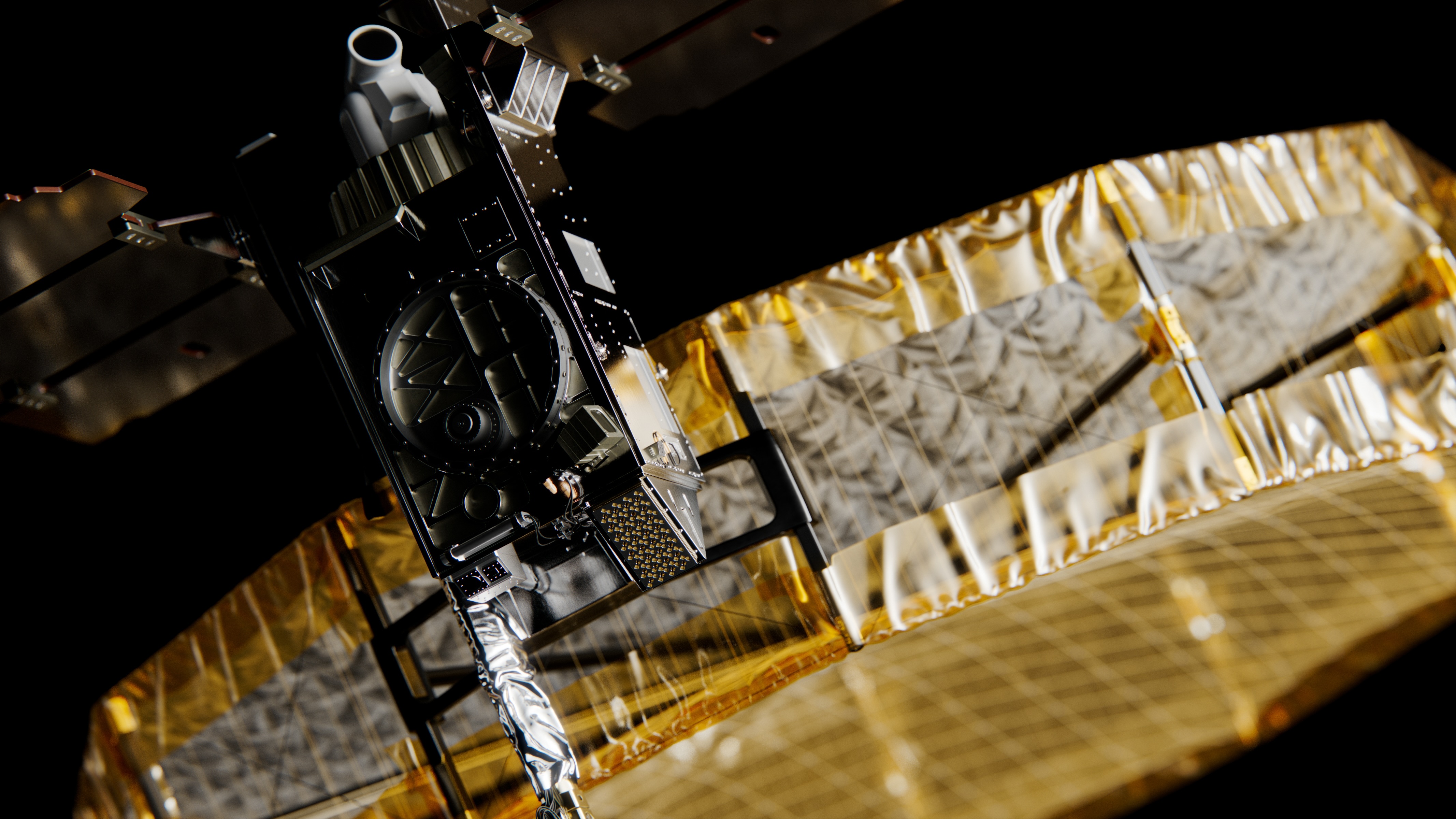
SAR satellites are demanding hosts. The radar payload is power-hungry and thermally aggressive. IonQ’s deployable antenna, allowing industry leading signal to noise requires specific bus geometry, constraining where other components can be mounted. Attitude control requirements during a SAR collect are strict – the radar needs to hold pointing within fractions of a degree to achieve coherent processing.
Adding an OCT to this environment means managing a second precision-pointing payload – the optical terminal’s acquisition, tracking, and pointing (ATP) system must maintain micro-radian-class beam alignment while the satellite is simultaneously maneuvering for SAR collection. The optical head on the OCT terminal is physically large relative to the satellite bus; fitting it, managing its field of view around other deployed structures, and accommodating its power draw required significant design iteration.
Acadia-10 sits on the larger end of commercial SAR satellites — 175 to 195 kg and 700 W of solar array power. That mass and power budget provided the engineering margin needed to accommodate a second precision payload without compromising the SAR performance the satellite was designed to deliver. The optical head and its associated support hardware are physically substantial; fitting them, managing field of view around deployed structures, and handling the additional power draw required meaningful design iteration. That iteration was possible here because the platform had room for it.
What Comes Next
Acadia-10 has begun on-orbit operations and continues to support the evaluation of optical communications capabilities alongside the rest of our fleet. As optical relay infrastructure continues to evolve, technologies like OCT have the potential to further reduce task-to-delivery timelines for time-sensitive SAR applications. While this work is still progressing, it represents an important step toward a more connected, lower-latency future for Earth observation.
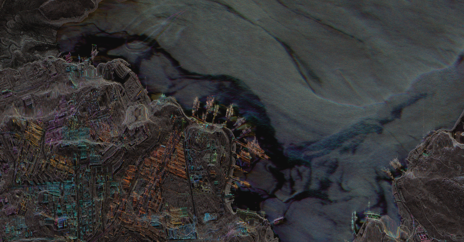
To discover more about Acadia-10, check out our first-light imagery at ionq.com
Curious About the Benefits of OCTs?
Optical communications terminals are reshaping how satellites exchange information, unlocking faster, more secure, and more efficient data transfer in orbit. Learn more here.
Curious Which Of Our Analytics Partners
Can Support Your Mission?
Contact our team to explore the possibilities. Our experts can help
you determine the optimal solutions for your unique needs.

Keywords

Stay Informed. Stay Ready.
Get briefings on new capabilities, technology improvements, and upcoming events.


.avif)